Products
Showing all 8 results
-
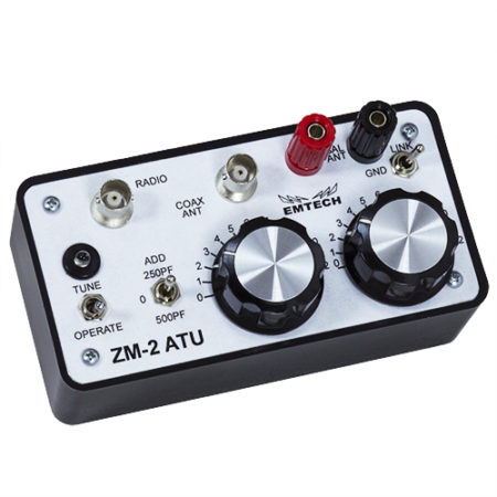
ZM-2 – BNC Connectors – Prebuilt
$105.00 Add to cart -
ZM-2 – BNC Connectors – Kit
$72.00 – $83.50 Select options -
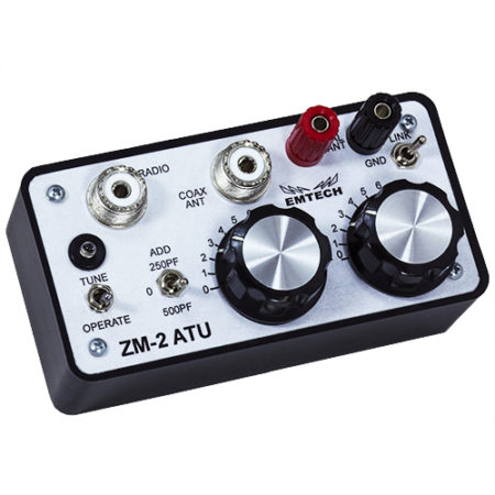
ZM-2 – UHF Connectors – Prebuilt
$105.00 Add to cart -
ZM-2 – UHF Connectors – Kit
$72.00 – $83.50 Select options -
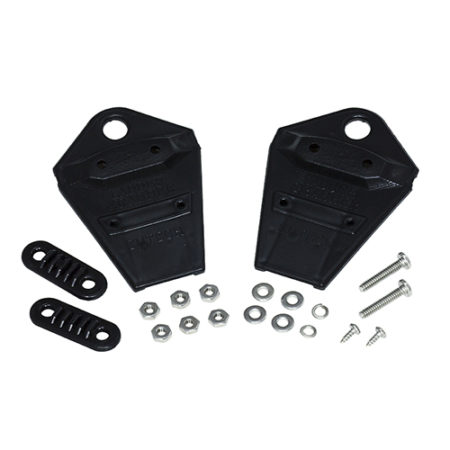
Ladder-Grabber
$8.20 Add to cart -
Coax-Grabber
$8.20 Add to cart -
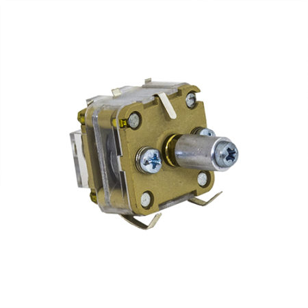
Polyvaricon Tuning Capacitor
$4.00 Add to cart -
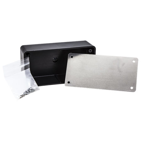
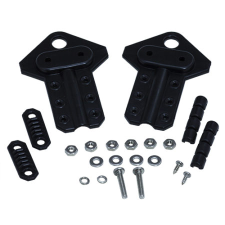
Project-Box-01
$5.20 Add to cart